Geomechanical Musings
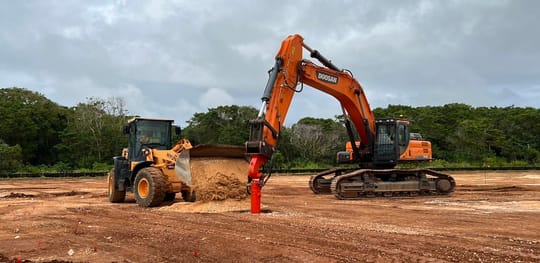
Any method that we deploy to solve engineering problems is an engineering tool. This is a note about the importance of trust while solving difficult design and construction challenges.
Read
Infrastructure stimulus projects will almost certainly be part of our economic recovery. Continuing our conversation about Pandemic Strategy, this article focuses on the likely stimulus rollout schedule and, during the interlude, what strategic actions we should take to prepare.
Read
This is a message of optimism and hope, of an opportunity long awaited that is finally set to arrive. But you need to read to the end to get to the positive, encouraging part.
Read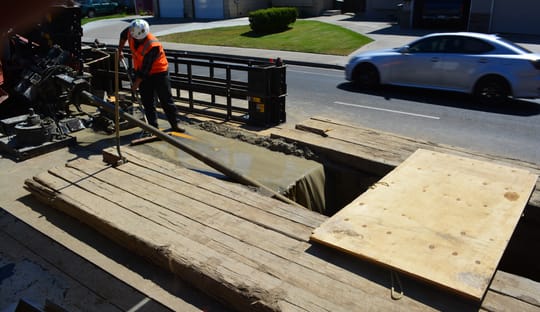
Each of us has at least one hilarious-yet-costly story about hitting an underground utility. The one I can contribute is from 1990 and lacks drama, so I mostly tell other people’s stories. Popping the water main in freezing Gillette, Wyoming on the Wednesday before Thanksgiving is a popular one. So is that one time the CPT rig successfully located the refinery’s hot crude feed. And I like to tell the one about the train that broke the gas pipeline and burned down the bridge even though there’s no drill rig involved. The best stories feature spectacular property damage and a complete absence of injuries or fatalities. In reality though, many of these stories do involve injuries or fatalities. They happen, and we know about them, but we don’t tell them. Despite our lighthearted anecdotes, underground utility protection is serious business. Deadly serious.
Read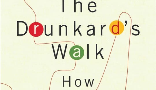
I have recommended this book to many of you. It was pivotal for my career and yet is specifically not a self-help book. It is filled with facts and observations, but has no advice or recommendations. It sets up the problem; the solution is left to the reader.
Read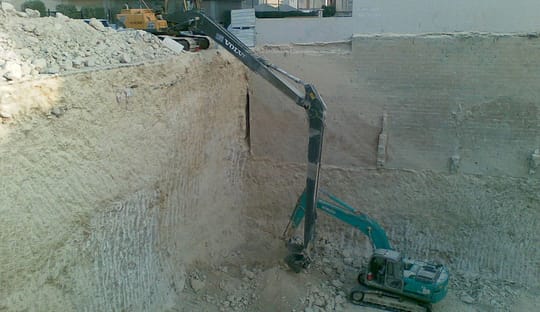
The best children’s story is Mike Mulligan and his Steam Shovel. About this there can be no debate. It was my favorite story growing up, and it remains pertinent to my work today.
Read
The Atlas Geotechnical crew is privileged to work all over the world, collaborating with squared-away engineers of varied backgrounds and sharing stories that range from tall tales to practical advice. I've learned that every community includes at least a little folklore in how they design and build. Always there is some inexplicable local practice, unique to the area and unknown elsewhere, that designers, regulators, and builders all assert is necessary to project success.
Read
We've got a particularly interesting problem on our desks here at Atlas Geotechnical. There's a lot at risk, various stakeholders are frustrated with and suspicious of each other, and there's not enough time. While working this problem through to a pretty tidy conclusion this afternoon, it occurred to me to share the process that we use to achieve a safe, efficient design.
Read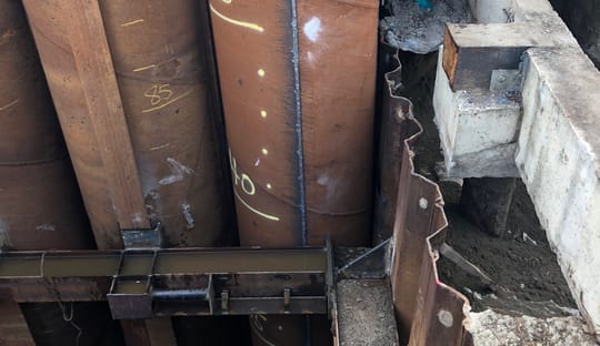
One of our projects achieved a significant milestone on Friday, exactly according to plan. Like most of our projects, it's interesting construction at a unique site, and there's no similar recent project to guide design and construction.
Read
2019 started strongly here at Atlas Geotechnical, but almost immediately we found ourselves overwhelmed re-working problems that we thought we had solved. And that re-work distracted us from other commitments, to the point where we nearly landed on one of our project's critical paths. And of course when we're working faster than we should small details don't get checked, like the PE expiration date on a permit drawing, causing more re-work. As soon as we frantically cut off one head, another grows in its place and the project continues to disrupt our workflow.
Read